Icicle Effect

This Icicle effect was a project to familiarize myself with Niagra's particle system, and an opportunity to utilize Houdini's simulation abilities which I brought into UE4 as a vertex animation.
This effect was an exploration of several things for me, as it was a first-time exploration of Niagra to begin with, but also an experiment with rbd simulation done in Houdini that was then brought into UE4 as a vertex animation.
This was done in Unreal 4.26 and Houdini 18.5.492
Houdini Simulation
To start the endeavor, I needed a simulation of my icicle falling to the ground and shattering. This required a rigid body set up and solver, and I also incorporated a rbdpaint node to increase the shattering/fractures at the first impact point for a more visually appealing destruction.

Within the solver, I also manipulated the forces to apply a wind that created a sort of ‘bounce/lift’ so the pieces didn’t simply hit the ground and immediately grow static.
Export and bringing into UE4
With our simulation ready, next comes the export. I accomplished this using SideFx’s vertex animation textures ROP, which is part of Sidefx Labs.
SideFx’s own walkthrough on the exporting process worked like a charm. Their video for this process is here.
Although the export worked without fault, I found three issues as I tried to implement the new vertex animation into my niagra vfx system.
Problem Solving
Issue 1: The scale of the vertex simulation was far too large, and resizing the vertex animation in its particle emitter resulted in erratic motion and broke the simulation.
Solution: Resizing of the vertex animation has to be done on the Houdini side of the pipeline, not in Unreal. Luckily resizing is straightforward as there’s a setting within the vertex animation textures ROP itself.
Issue 2: The simulation played indefinitely regardless of whether the emitter was paused or playing. There is no way to properly time the simulation to the rest of the effect as it’s incapable of being paused nor does it have a beginning/end set.
Solution: Diving into the material of the vertex animation allowed me to discover a solution.
The default material for a rigidbody VAT provided by SideFx looks like so:

By modifying this material, I was able to plug in a dynamic parameter to the ‘Time’ pin...
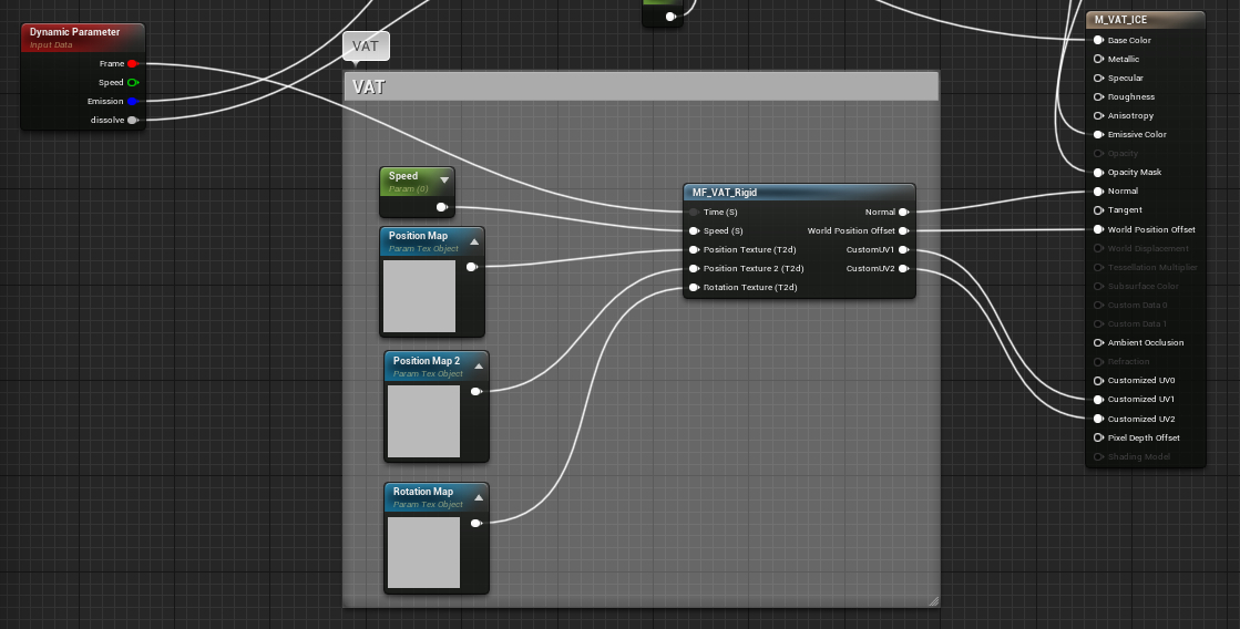
...which then let me have control over the playing of the simulation within the niagra emitter. This method also had the added bonus of letting me speed/slow the timing of the simulation merely by adjusting values in the curve of the Frame portion of the dynamic parameter, meaning I wouldn’t have to go back to Houdini and reexport the simulation for minor timing tweaks.

Issue 3: The Vertex Animation when exported, does not completely match the appearance of the simulation in Houdini. In particular, the first frame of the simulation does not match. This issue is brought up and known by SideFx in their documentation, however I still had to find a work around.

Above is the difference between the mesh put into the simulation (left) and the starting frame of the simulation after exporting the vertex animation (right).
Originally in the VFX system, I used a static mesh in the first half of the effect, which I then swapped out for the simulation in the second half when the Icicle is destroyed.
However the differences between the two icicles were too noticeable. In the end, I had to ditch the static icicle mesh entirely, and use the VAT Icicle for both parts.
Luckily, this was possible thanks to the dynamic parameter for the frame, as mentioned in issue 2.

Instead of playing the animation this time through the curve, I kept it static by holding the first frame.
Conclusion...
I was concerned about layering all the various elements needed for the Icicle material onto the VAT, however through the course of the project, I found building in the same VAT material didn’t create any issues. The Icicle material is the most complex material I’ve made, it contains an opacity mask with an emissive border that can swipe the crystal, a dissolve effect, along with the VAT and a base emissive value that works separately from the emissive line on the swipe effect. I wasn’t sure all these elements would be able to work together initially, but the VAT proved to be less daunting to work with than I initially feared.
The ending node system for the Icicle...

Valerie

Valerie was a project with a focus on getting an atmospheric glowing effect in Houdini without the use of post-processing and compositing. To do this was a process of trial and error to find the right combination of light geometry and volumetric rendering.
We will be creating a moth that flaps its wings and emits ember-like particles. The moth will glow through the night with an emissive light.
First- Making The Moth
To start, find or create a reference image for the shape of the wing. We will be creating a curve to follow the shape.
To bring in the image, press the ‘d’ hotkey over the viewport, then navigate to the ‘Background’ tab.

Select the proper view tab (we’ll be using ‘front’), then select the disk file of your reference. The bottom of the wing that connects to the body should be placed along the zero axis, as we will be mirroring this geometry later and want a clean connection at the bottom.
‘Auto-Place Image’ by default will be clicked on. Click it off and adjust the offset to get the proper position manually.
Now that we have our reference image in scene, drop a geo node at object level and then drop a curve node. Starting at the zero line, click along the edge to get the proper shape and close the curve.

By default, the primitive type on the curve node will be polygon. Change this to ‘NURBS’ for a smoother curve. Check the ‘Close’ box as well to fill this curve in.
Next, we give the moth a completed shape. Drop a transform node and put rotation in the x axis (I put a value of 19).
Drop a mirror node, setting the direction to ‘Z’

We now have a full moth with its wings slightly parted. Now for animating it. Drop a transform node before the mirror node. By setting keys in the x rotation our moth will be able to flap its wings. Drop a null node to complete the moth’s geo node.

Our network.
Particles
Create a second geo node. Inside, drop a ‘file merge’ node that references to the ‘valGeo_OUT’ null node from the first network.
The particles we will be creating should be affected by the movement of the moth’s wing animation. Drop a ‘trail’ node setting the result type to ‘Compute Velocity’. I scaled down the velocity scale to 0.6.
Now using the particles tab on the top menu, create a ‘source particle emitter’ using the wing geo.

Our ‘Pop Source’ should scatter on the surface and use first context geometry. The birth tab:

The life variance and probabilistic emission will give a variance to the spawning particles.
The Pop Force node applies some noise to the particles, but scale this down to be less extreme.

Finally, close the geo node with a null.
Fog
Create a new geo node at object level. The fog is a straightforward network of one node.

A low value keeps the fog from overwhelming the scene. In the properties tab, you can tone down the display density as well. (I used a .85 value)
Lighting
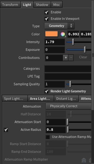
In order to get a glow-like aura of light around the moth, the moth will need to be a light source in the scene in order to affect the fog. Using the lights tab on the top right shelf, use the ‘geometry light’ option and select the moth.
Without the right settings, the moth will either be washed out by the fog, or the fog will illuminate too strongly from the intensity of the geometry light.
To keep the moth bright use a high intensity, and modify the 'attenuation' tab values to keep the light from spreading through the entire fog.
The particles should have a color as well, but do not need to influence the fog as strongly as the body. Navigate to the material palette and create a glow material. To assign this to the particles, navigate to the object level. On the geo node for the particles, go to the ‘render’ tab and select the glow material to assign it.
While we’re here, we’ll modify other settings for rendering the particles. On the geometry tab, we’ll want to change the sphere to circles and we’ll want to reduce the scale to about .2
To make sure our lighting settings influence the scene, we’ll have to modify settings on our render node. Our glow will fail to show in the fog without a ‘volume limit’ value set.

Ta-Dah!
Procedural Brick Wall Script

This python script creates a piece of brick wall geometry, with row heights and brick lengths that are generated randomly each time the script is ran. The user is able to modify variable values as needed for things such as: the minimum height/length of a brick or row, the X & Y dimensions of the piece of generated geometry, the depth of the bricks when extruded, and the bevel offset of the brick faces.
From a coding standpoint, the final result of this script is vastly different from my original concept on how to tackle the challenge of creating a brick wall generator through code. When I began this project, my idea was that if I could scatter points onto a plane, then I would be able to then instance cubes onto the points and set each cube's size to half of the distance between it and its closest neighboring points in Y, -Y, X, -X. The scattering of the points was done through a geometry node that was converted to vertices. I thought this method would be ideal due to the highly random placement of the points. However as I worked on this method, I found too many issues in using the vertex positional data, and had many issues with overlapping geometry among other things. This led me to search for a different method.
My second plan was to still use scattered point data, but rather than instance cubes onto the points, I would use the position of each point as a subdivision location on a plane. I thought that if I created a highly irregular "grid" of sorts, I could then have the code randomly dissolve edges in the plane to create a unique and interesting arrangement of faces. I found issues in this method due to the nature of how Blender's modeling works. I found cutting edgeloops required user mouse input, and that using values from the vertex locations to set the edgeloop positions wouldn't be possible. After this, I then wondered if I could just extrude the random vertices to create lines rather than needing to cut a plane, which led me to my final method.
The actual method used to generate the brick wall, is likely the simplest of the methods concepted.
First, the code creates a path and deletes all but one point at the origin. This path is extruded once before it is converted to a mesh and all the extra vertices are dissolved. (This step is necessary as Blender appears to hate when you have only verts in a mesh, so if you start with a path you are able to have an edge instead of a vert.) This line is then extruded randomly to create the "rows" of our brick wall.
Each segment of the line is then extruded to create "bricks". The code runs through each segment until it fills the row to the minimum length.
Finally, the faces are extruded outward and beveled, and thus the wall is created.
Overall I enjoyed working on this script, despite struggling with Blender's peculiar behaviours that scripting in Maya had not prepared me for.
Procedural Brick Wall Geometry Nodes
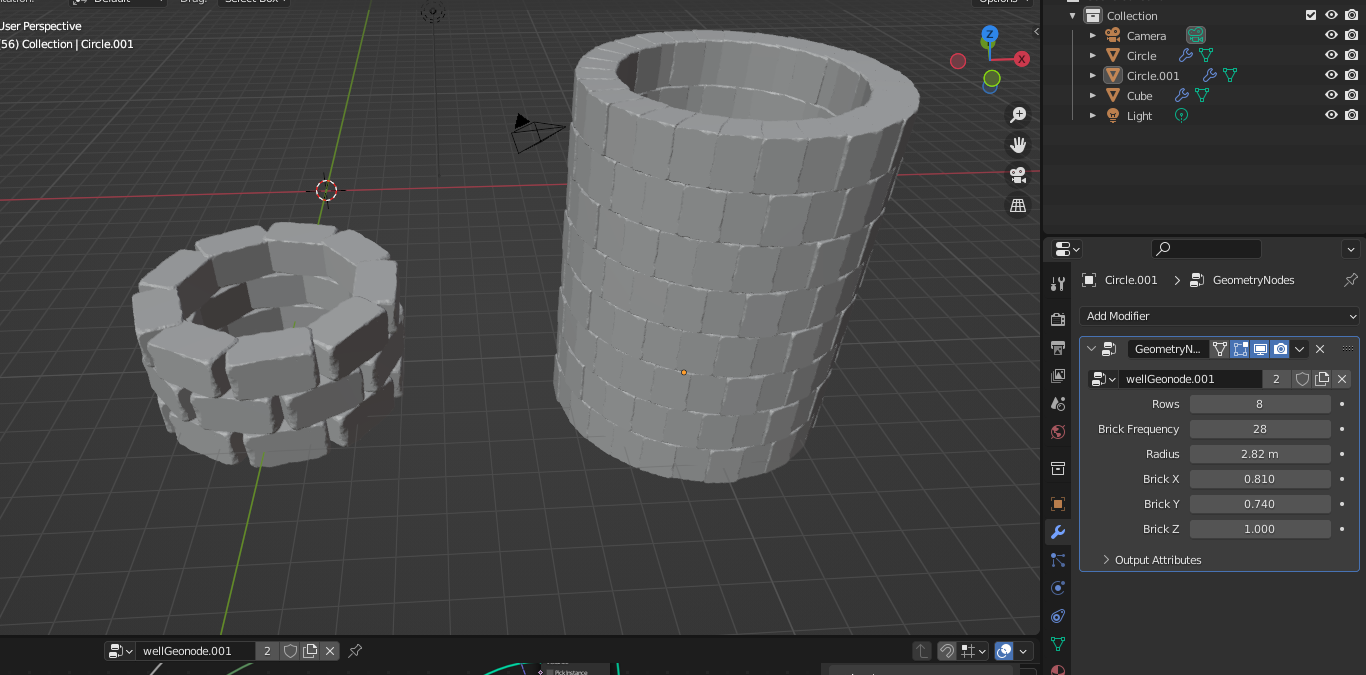
Using Blender's Geometry Nodes, the user is able to create a procedural brick wall with customizable variables.